Glass Garage

Rev. 2001-12-20, 2002-01-27, 2003-01-21, 03-06, 2004-03-12, 2006-05-04, 2007-03-14, 2010-03-04 (edits)
[Search on date pattern to find latest changes, more than one may be found.]

Return to Sitemap

Other pages
Annealer Construction Controller


Garage at Houston Glass
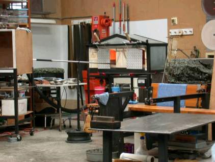
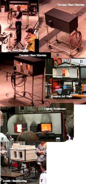
A glass garage is a hot place to store pieces of glass while still working on them. It is normally kept just above annealing temperature and below the point that the glass starts to sag.  Often the garage is heated by gas and literally looks like a two car garage. (Right) (Link to image of several garages)
 Temps may be uneven and often set by guess/experience without a controller because of cost.  The cooler side is supplied with heat by adjusting an opening inside between the two parts.
 I chose to make mine electric.  This page shows drawings and pictures of the design I worked up and built during November 2001.

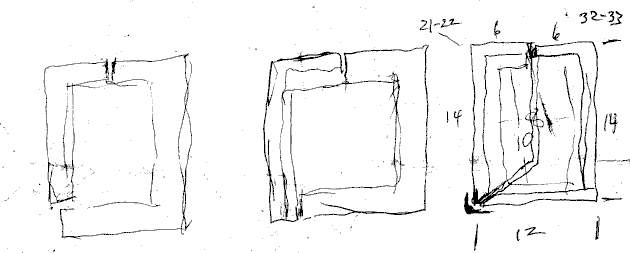
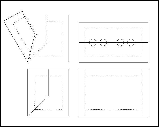
The design process consisted of making little pen and pencil drawings to try and get a feeling for what I needed. I had thought about having a garage on and off for several years, but drawings brought it into focus and adding dimensions jelled the ideas.

This is part of the page on which I did the rough sketches after the thinking. I knew I was going to wrap the thing in sheet metal and used the bent edges of the sheet metal to hold the frax in place while using the frax to protect the sheet metal. I considered a curved outer shell, but rejected it after considering what changes or additions I would have to make to set things on the bottom inside and to set the unit on a surface. Drawings in planning of glass garage.

I knew I wanted/needed an opening on the top to put in pieces hanging still on the pipe or punty. The question which had challenged me as time passed was how to open to box to get things in. A symmetrical division, like a pair of boxes face to face, would require an odd mount to open and distort the bottom on opening preventing parking stuff there.

  So the first sketch on the left proposed a symmetrical split at the top, with the front hinged off the bottom that extended under to the front - items would have to be lifted over the back edge of the door insulation.
. A second choice was to extend the front down and hinge it at off the bottom behind it, which seemed to put a lot of weight out on the edge of the doors bottom flange and create a jam point just above the hinge.
  The third choice merged the first two - to hinge the front at the corner.
  Having visualized the three choices, I began to think through the arrangement of the sides - how would the sheet metal be arranged and where would the frax overlap. Arrangements like the first two seemed to leave unsupported frax and awkward corners as the frax in the front met the frax on the sides. I suppose it could be worked out, but seemed easier to have the side sheet metal and seams follow a logical dividing line (right) that left a full opening with a flat bottom.

Then I began to apply some dimensions. I didn't want this to get huge, even though my first annealer had only 1.5 cubic feet of space and 6" of frax all round (making it 2 x 2 x 3 feet outside.) For this one, I would use 2" frax. That allowed me to begin putting some dimensions on the pieces I might put in. After some playing, I decided that 10" top to bottom and 8" side to side would serve me until I got a lot better, especially since hanging garaged pieces are not necessarily done or full sized. With 2" frax that gave me 12" front to back outside and 14" tall. With the same space for two items side by side, 8" each piece would be 16" wide inside, 20" outside.
 

Drawing of sheet metal garage for storing hot glass objects while workingAfter going to the drafting program, this is the result (click for larger) A piano type hinge will be along the lower edge. The frax blanket will be cut long to fit against 1" tabs on the edges. 1/2" frax blanket will be compressed on the seams of the opening to seal the opening and guard the metal. The metal will be cut back on top to clear the shafts of hanging pipes/punties and frax will be added if needed to seal around the shafts. After some thought, the side frax walls will be full sized (12.5" x 14.5") and the center frax strip will hold them in place, so it will start at the top and run all around and be about 54" long (2" over size) and 16.5-17" wide to press against the sides. (The alternative of fitting the side pieces inside the long piece does not work well, from experience, as they tend to shrink and fall out.) A kiln shelf or frax board will aid setting things on the bottom. A brace will be added to support the hangers. A brick or cast block will get the terminals of the element out and it will be near the top to avoid close contact with the hanging piece.
Still needs a handle. May need stiffening on top when cut flanges for access holes.


Today, I pop-riveted the third and fourth side panels in place - in the process reminding myself why I shouldn't drag projects out, as I folded a piece that shouldn't have been. Worked carefully to keep door aligned as it became stiffer. I then added pop-rivets to mid positions on many locations that had only had corners riveted. Finally, I added a strap steel handle for the door. The door, when bare, keeps flopping open. If it continues after frax is added, I will have to add a latch or weight to keep it. 2001-12-02 Complete shell of garage with handle, before latch and chain added
2001-12-20
This is one of the first pictures taken with my new Nikon 995 digital camera, which I like a lot. This is actually reduced in size from what was taken.

At this point the 2" thick frax blanket has been installed for one side and cut for the other. The blanket is very stiff and it was cut about 1/2" oversize so it would jam in behind the flanges. The overstuffing protects the flange from heat leakage.

In the upper corner is a small chunk of insulating firebrick with two holes for the element leads, glued in place with silicone sealant, which will handle up to 400F. (Detail below and here.)

Glass garage under construction with insulation cut
Here the long continuous center piece has been installed. Both the side and center pieces were installed using water glass (sodium silicate) as a glue that will stand higher temps. When cut to the length measured with a flexible tape, it came out about 6" too long when folded around the corners. The 1000 watt element is hanging in the corner. About 3" of wire was pulled out straight at each end and the blanket was sliced to allow straight passage. [The piece of insulating fire brick has its holes in the middle. It was installed with its edge beside the 2" side insulation, so the holes are behind the 2" body insulation. So either the body insulation had to be cut a bit to pass the wires, or the wires had to be bent around the insulation, or the insulation had to be pushed aside. I chose the first.] Glass garage at completion if insulation instaltion with unstretched coil hanging down.
Next, the coil was stretched and pinned to the frax and connections were made to the ends with copper split bolts for the power line, with the ground wire screwed to the shell. A hole was drilled between the right hand and center cutouts to install the K-type thermocouple, which has a small L bracket screwed beside it to support it. It extends about 2" below the frax.
These three pictures show details of the glass garage. At right is a shot across the lid of the body, showing the mount for the thermocouple, the base of the latch and the reinforcing bar. The power connection is at the top.

At the lower right is a close up of the connection of the 14 gauge wire power to the coil, the ends of which are brought out through a T-shaped block of insulating fire brick, joined with copper split bolts and slathered in clear silicon adhesive. The ground wire is screwed to the shell. The ends of the coil are straightened (but not doubled in this case) to reduce the heat load coming out.

Below is a shot inside, with the coil pinned to the back and the top of the body and the thermocouple end inside the unit. 2001-01-08

Connections on edge of glass garage

Coil in glass garage also thermocouple Main power connection on glass garage


Drawing of frame for holding glass garage at convenient height, with pipe hanger.
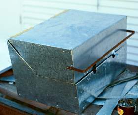
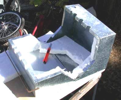
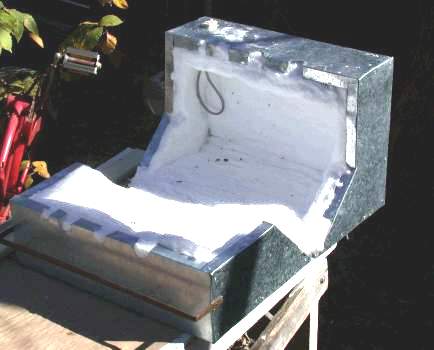
The two halves of the box are made of different sheet metals and it really shows how gauge is measured. Both are 26 gauge, but the body is made of galvanized sheet metal, which shows a large swirling grain pattern, while the lid - toward us in the picture above - is plated steel, showing smaller grain in a much more even coating. Because the plated is a thin coat, it affects the amount of steel - there has to be more steel because gauge in America is actually a measure of weight per square foot, not thickness. Less zinc = more steel, more steel = harder to bend. I feel I am going to have to add a stiffening piece to the body because the latch applies enough force to bend the sheet metal out of line. [Done 2001-01-06 see above right.]
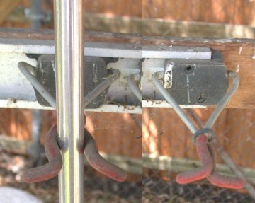
Pipe hanger using cross arm broom hangers.I built a frame to hold the garage at a good working height, to allow easier movement, and to provide a bar for hanging pipes or punties, as shown at right. It is welded of 1/2" steel tubing with a wooden bar.  The hanger mounts are X-shaped broom hangers that use gravity to tighten and are rather long. The location of the upright depends on how long the hangers are - if I had used V-type hangers or broom clips, I would have had to put the upright further forward or make the mount for the hangers thicker.  Small wheels mounted on the back permit easier moving.  Chain was added on the sides to keep the door from flopping down as it opens.  The unit is a bit springy and a brace was added under the shelf, which is adjustable to height. 

I have used the garage for several pieces.  It seems to hold at about 1000F without a controller - luck and likely to change with conditions.  It has to be used out from under my shed roof as the punties and pipes hit when angling pieces in and out.  The cross bar broom hangers use gravity to pinch the hung item and they seem to work well, without requiring an exact match on the collars on the pipes.  2004-03-12
 

Contact Mike Firth