House - Rental - My first wife
and I lived in a rented apartment while in Dallas and we rented the one upstairs
for the last years of our marriage and my first year or so divorced. I
believe I drilled through to run wires between two closets. I definitely had an
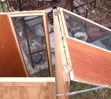
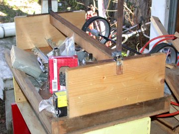
odd room off the maintenance building beside where the school bus
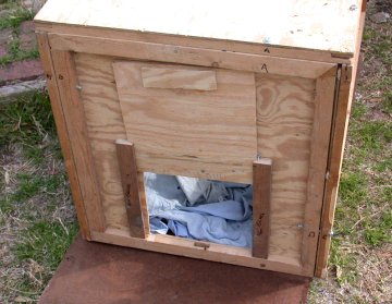
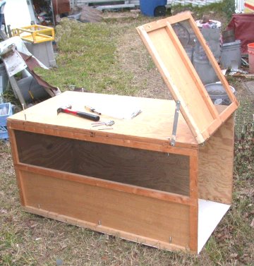
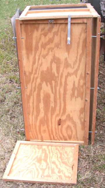
camper was parked which supplied power. I had a swing
up hatch door that allowed me to walk in under the shelf that gave bench space.
There was one small window.
When I moved out of the apartment, I lived in a duplex among blocks of duplexes
called Northway Duplexes between Matilda and Greenville. I added
insulation to the attic space, put a mail slot in the door, and replaced a
broken window pane with a box and ramp for the two Siamese cats that became
mine. The garage space behind was stuffed. When it was announced that the
places were to be reconditioned and after pets would not be allowed, I removed
the insulation and took it with me. Later, many of the duplexes were moved from
their slabs, some to near where I live now, and multistory condos and apartments
were built on the space.
The house I was renting when I married my second wife was literally pulling
apart by the time we left - the foundation walls were tilting and it had been
hit in the corner by a loose car from next door. During the time I was there I
could customize it, because it was old and was ignored by the landlady. My
"half" of the house was the original downstairs living room and kitchen,
stairway and upstairs central room, bath, porch, bedroom and attic space. The
other part was the parlor, living room, and kitchen with bath to the side -
walled off from mine side. I installed a cat exit box and lots of shelves in the
downstairs space and stored my tools, etc. there. The upstairs porch had
two walls of windows and I made it my first bedroom, adding insulation and
covering the windows. A single window air conditioner in the bathroom with
plastic air ducting awkwardly served, although I slept on the floor in the
bathroom during the horrible summer of 1980. Heat was provided by unvented space
heaters to which I added thermostatic and safety control. I insulated and
sheet rocked the front "attic" space to have a queen sized bed. 2011-02-22 |
|
Done: heating system, gas plumbing, electricity,
sewer, water, leveling, insulation, chimney, roofing, garage, kitchen, grey
water drainage. I like living in an old house. I like making changes
and in a new house the changes would stand out as well as the incomplete jobs.
See notes on rentals above. The house was in nice visible shape, but the
floor sagged and was out of level so much the dogs learned to drop a ball in the
living room and chase it as it rolled into the kitchen.
Over the
course of time, I did all those things listed above, assisting on the
first with my father-in-law and his workers doing most of the skilled stuff.
Gas plumbing included the line to the furnace in the attic and removing extra
pipes to unused heaters as well as adding plumbing to move the water heater from the
kitchen to a utility porch, add a gas dryer and move the cooking from a stove on one side to a cooktop
and dual ovens on the other side.
When we moved in electricity was supplied
through two circuit breakers in a box limited to six and all the wiring was old tube and
post. First the box was filled with breakers and wiring changed to
grounded Romex and eventually the service was upgraded to 200 amp, new from the
utility connection on and I did it with a home owners permit after taking a city
test.
When
the sewer line started breaking down, the first part was done professionally,
but the rest was rerouted by me around the garage in a trench with a rented
tractor trencher. Later a rented smaller trencher was used to dig out the
hole for a new tree to replace a broken one and while around, trenches for
burying electrical and gas across the backyard to garage, glass hut and back lot
line were cut.
During leveling, one chimney was found to be resting on the
house, making it sag, and was removed brick by brick from top and bottom with a
pal.
The house was leveled gradually with hydraulic bottle jacks and mounts that let
me slip the jack inside, raise the house 1/2", add shims and remove the jack for
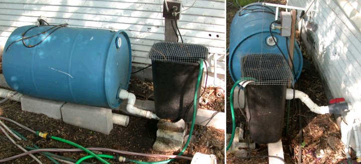
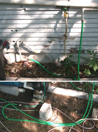
use in another location. In one wet location under the bath, where driveway
water drained under the house, over 3' of concrete post 6" across was pushed
into the ground to get a secure footing. Concrete curbing was poured or
assembled to divert ground flow and gutters with extended piping moved up to
3/4's of the roof's water to the front street gutter rather than down hill to
back yard.
The other chimney was trimmed from the top and the hole shingled over during
reroofing done with a nephew and one hired guy,
finishing on some of the hottest days of the year, and damaging the ceiling in a
strong rainstorm when the blue tarp blew free.. A rented pneumatic stapler
and purchased trailer let me take off four roof layers (old rolled granular,
wood shingle, two asphalt) and meet the insurance
company's needs while they paid for it due to a nasty storm in the spring. 2005-07-29
rev. 2009-02-21
The kitchen rebuild was a major project done
during and after the house leveling and gas plumbing rebuild. When we
moved in the kitchen was usable, but the counter was installed lower than
average, preventing putting a dishwasher under it and the cabinets under the
counter had been sawn away to accommodate a double sink. The two wall
cabinets were apparently original to the house and thin sheet rock had been
installed around them. There were two closets, one fairly recent with the
water heater inside and another original to the house with a door that opened
along the wall (not into the room) over a window. Our first step in
planning was to move the existing gas stove across the room and fix the gas
plumbing for a planned replacement and double gas oven, there not being enough
electrical for electric appliances and us preferring gas anyway. After
more planning, the water heater was moved to the former back porch which had one
of two walls of windows removed and the wall rebuilt solid and a smaller closet
built for the water heater. Water, gas and drain plumbing were extended
under the floor to make a utility room with gas dryer, clothes washer, and chest
freezer in line along the wall. The large and small closets in the kitchen
were ripped out - we found original wall paper in the small closet.
As in other parts of
the house, the walls were planked with shiplap on the inside. The window
just outside the old closet was shortened to allow base cabinets across its site.
We bought assembled cabinets from Home Depot. Following a lead read
somewhere, most of the lower cabinets have drawers rather than doors, much more
convenient. The ceiling is almost 9', so we gained more storage space by
putting in 42" tall cabinets on the walls and improved access for 5' tall Gigi
by lowering them until a Kitchen Aide mixer would just slide under. New 20
amp electrical circuits were brought down from the attic, 2 on each wall but the
entry, so there is lots of power available for counter top use.
[Images below]
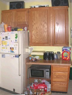
When
standing at the entrance, starting on the left, there is a refrigerator freezer,
then a microwave below the counter and silverware drawers with dinnerware on
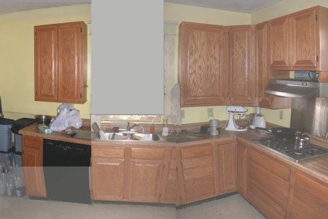
shelves above. Stepping to the right to the SW wall, There is dog food and
garbage containers, a small cabinet of cleaning stuff next to the dishwasher
with canned goods above, then a double sink with disposal and window over, then
drawers with storage containers and baking glassware above. A lazy susan
corner cabinet holds bulk food goods like flour and rice leading to the gas cook
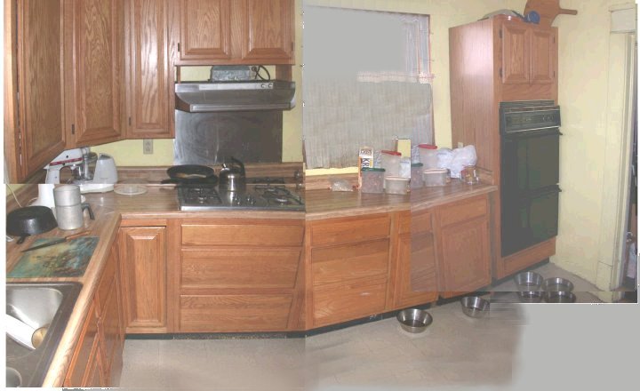
top with vent and small storage over and cooking tools and pots and pans below.
Another wide set of drawers is under the side window with narrow storage filling
out the length to the gas double oven in the corner with storage over and under
it of baking sheets and broiling pans. Total cost of doing the kitchen,
with myself and Lynn White doing the work except for the counter fitting, was
about $3,000 including appliances. Besides lowering the tall cabinets, the
dual ovens were mounted lower than average and the microwave was put under the
counter instead of above to accommodate Gigi's height. 2007-10-30 rev.
2009-02-21
Projects List
|
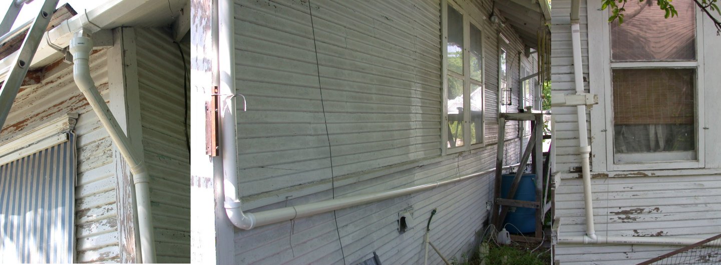
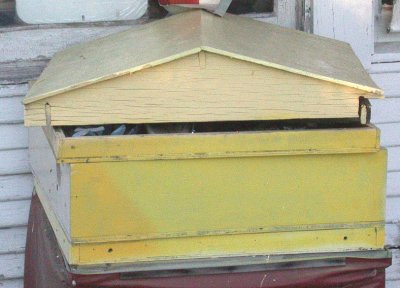
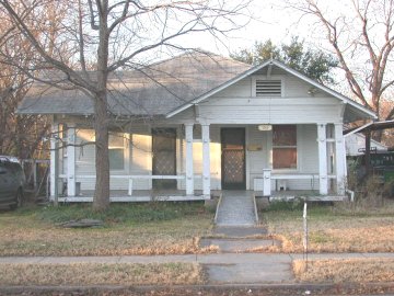 Our
house (left), not
our house (below), but similar construction in same area.
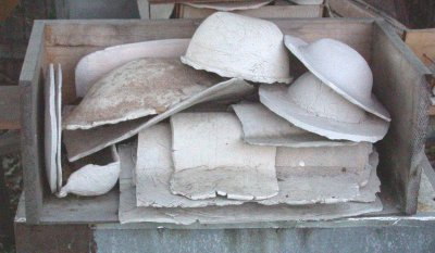
Our
house (left), not
our house (below), but similar construction in same area.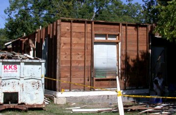
 P
P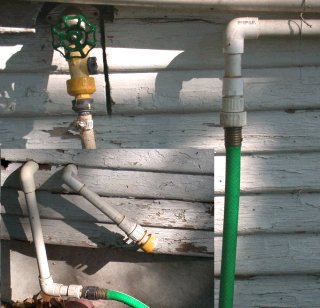
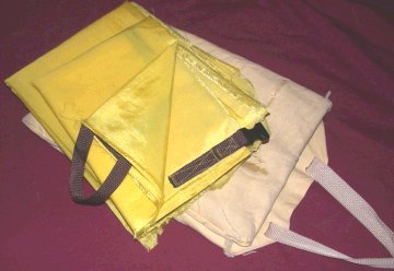


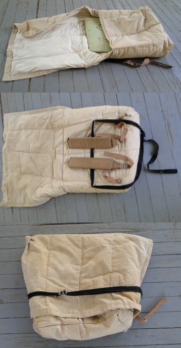
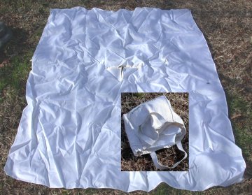
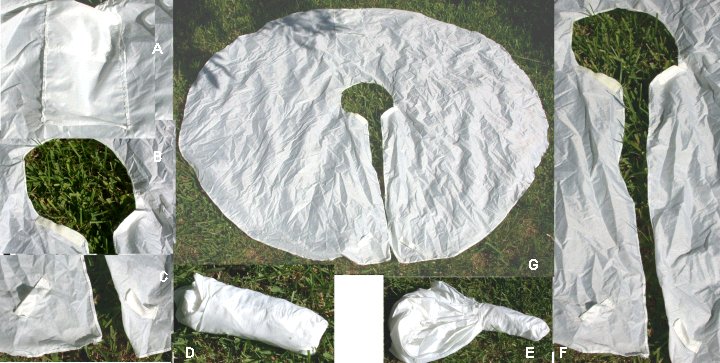
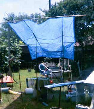
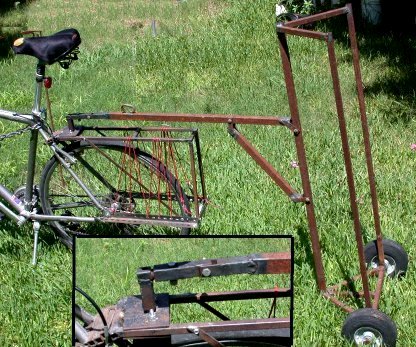
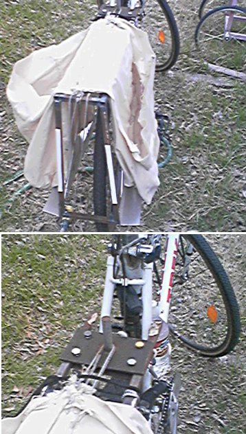
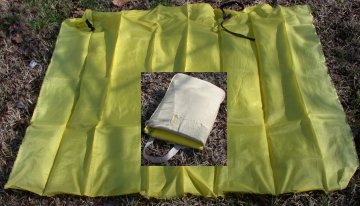 So I came up with the idea of a wrap around skirt with a buckled strap at the
belt line, which worked very well, especially if I maneuvered it so the wind
did not enter the overlap slot. A quick release buckle allowed adjustment by
sliding and fast removal. Then I came up with an addition
that was even better. The fabric was slightly bulky and awkward, more so
than the ripstop used above, so I wanted a
So I came up with the idea of a wrap around skirt with a buckled strap at the
belt line, which worked very well, especially if I maneuvered it so the wind
did not enter the overlap slot. A quick release buckle allowed adjustment by
sliding and fast removal. Then I came up with an addition
that was even better. The fabric was slightly bulky and awkward, more so
than the ripstop used above, so I wanted a 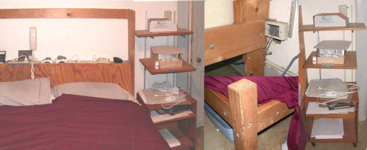
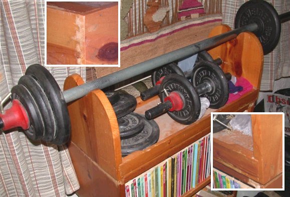
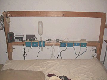 The current bed is built similarly, but the side and foot rails are 2x6
with rounded over corners which are tenoned into slots in the corner posts which
are rough cut 4x4's. The headboard this time is quite shallow to give more
room in the bedroom and is made of 1x4's across which are screwed to the wall
and bolted to the platform, 1x8's on end for end legs and a 2x4 across the top
to form a shelf. Tilted plywood panels give a surface to sit against, being a
stop for pillows and concealing the wiring. In and on the narrow shelf are
two heating blanket controls, LED alarm, phone jack, ceiling fan speed control,
dimmer outlet for reading, X-10 remote control console, multiple outlets
for plugging in the former plus heating pads and my wife's audio reading
equipment. A reading light is clamped to my side upright and a phone is
mounted on the wall near the center. On my wife's side a box on wheels is sized
for Braille paper and books. Both sides have slotted standards for shelf
brackets. Just recently, I added an extension
to one of the foot legs (on my side) and put a carpeted cat climbing post and
platform for our cat. 2007-08-09, 2008-02-08
The current bed is built similarly, but the side and foot rails are 2x6
with rounded over corners which are tenoned into slots in the corner posts which
are rough cut 4x4's. The headboard this time is quite shallow to give more
room in the bedroom and is made of 1x4's across which are screwed to the wall
and bolted to the platform, 1x8's on end for end legs and a 2x4 across the top
to form a shelf. Tilted plywood panels give a surface to sit against, being a
stop for pillows and concealing the wiring. In and on the narrow shelf are
two heating blanket controls, LED alarm, phone jack, ceiling fan speed control,
dimmer outlet for reading, X-10 remote control console, multiple outlets
for plugging in the former plus heating pads and my wife's audio reading
equipment. A reading light is clamped to my side upright and a phone is
mounted on the wall near the center. On my wife's side a box on wheels is sized
for Braille paper and books. Both sides have slotted standards for shelf
brackets. Just recently, I added an extension
to one of the foot legs (on my side) and put a carpeted cat climbing post and
platform for our cat. 2007-08-09, 2008-02-08 
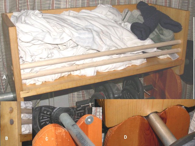 And more recently
built a tricky shelf to sit on the curved ends to hold night shirts and sox.
2009-08-02
And more recently
built a tricky shelf to sit on the curved ends to hold night shirts and sox.
2009-08-02
 This
is the
This
is the