Doors
to High Temp Locations

Return to Sitemap
Back to Equipment Sequence

2005-07-07 Rev. 2006-05-26, -11-11, 2008-03-03, -04-28, 2009-05-04, 2012-10-02 (minor edits)

Doors Intro
Furnace & Gloryhole
Annealer

Intro
Furnaces, glory holes and annealers in glassblowing require doors to permit access and seal in the heat. The problems include that the temperatures involved will destroy many construction materials, a door may get in the way of easy use, and many refractory materials are heavy and/or fragile.

There is a dividing line between annealer temps and furnace/glory temps such that it would be possible to build an annealer with all or mostly fiberglass insulation - if it were never taken up to sagging, fusing, or casting temps.  But the risk of total damage from moderate overheating and keeping options open, means that most annealers are built to handle temps up to fusing temps - 1500F.   Since furnaces and glory holes are rarely at that low a temp, the materials and mountings are different.

When building a door, the choices are sliding, pivoting, counterbalanced, split.  A sliding door can be horizontal or vertical.  For a person working alone, added factors are discussed here.

A sliding horizontal door door can be split or not and the wheels can be above or below the opening. Making a horizontal door requires a special mechanism or shaped track to seal the door closed and lift it clear of the seal when opening. Based on observation of the annealers at the Studio at the Corning Museum of Glass and a couple of electric furnaces, a lever is used to lift the door onto wheels and off the seal.  2008-04-28


Furnaces and Gloryholes

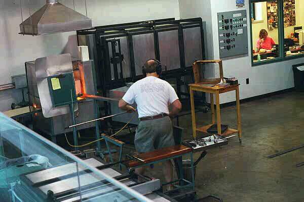
I will start with a history of doors on my equipment that all use the same method because they 
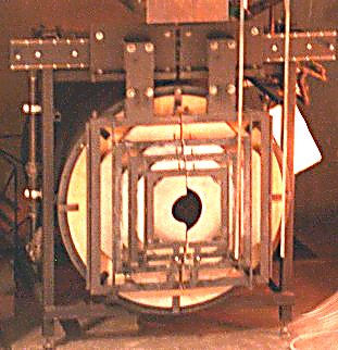
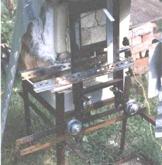
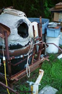
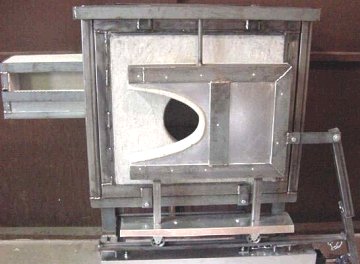
are simple and reflect my choices.  Then on to other examples.
At right is my ugly old/first furnace door with bad and good choices.  The refractory material was brick pieces clamped in a rough angle iron frame clamped by tightening bolts to move the lower edge.  The wheels are pulleys with bushing as described below.

Below is the first door for my furnace.  The door panel itself is insulating castable cast in a pie pan with cast in bolts for mounting.  The problems were that insulating castable is not very strong and the door cracked across the mounts.  Later versions (below) use a compression ring around the outside of the panel and bolted to a bar across the ring.

Very first furnace with door of insulating fire brick clamped in frame
Furnace door, cast, side rolling, drawing My second furnace with its first door.
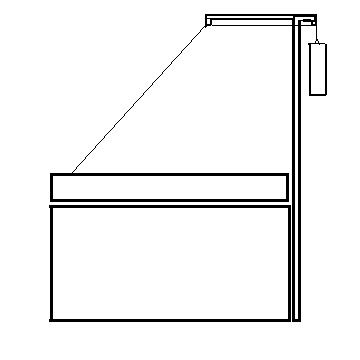
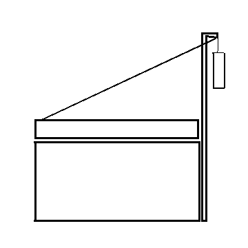
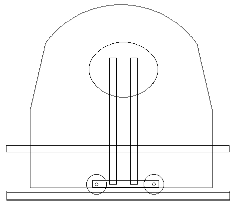
The sketches above and below clarify some of the details mentioned above and shown in the picture at right.  Included are the handle in the heat shadow (lower left of photo), the steel bar across the back from the ring around the rim.  At the bottom of the rim, barely visible is the bolt and angle to put the insulating castable into compression.Furnace door, drawing, side view, cast in ring and rolling Furnace door, cast in ring side rolling
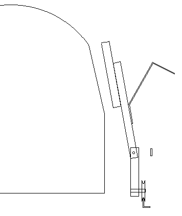
 This is the similar arrangement on a glory hole door.  Because the door is vertical, there is no pivot in the support.  The bottom rail rests on two brackets projecting from the legs and slides in and out to adjust to the face of the door.  The wheels are on the ends of the support for stability and are mounted to the front side so the door tends to lean against the front of the hole.  The guard rail that keeps the door from tipping too far away can be made out as an L near the post left angling down into the picture.

The wheels on all my door units are made by buying cast pulley sheaves with 5/8" holes into which I push oilite bronze bushings which are 1/2" inside diameter.  I use 1/2" bolts of the right length to have bare shaft to fit in the bearing and two nuts on the 1" of threading, clamping the angle of the bracket between the nuts.   If the door was solid castable, not insulating castable, it would be much heavier and if were thicker, it might be so heavy that true grooved caster wheels with ball bearings might be required but they cost several multiples of the pulley and bushing combination.

The door was cast by building the frame and laying it face down on plastic, then propping it up about 1/4".  The plastic was formed around the metal so the castable flowed to line up with the outer edge, thus forming protection for the steel.  A curved piece of Formica formed the curved edge.  This was a mistake as a steel should have be welded to form and support the insulating castable which shows a crack in this picture and the upper projection has had to be wired in place.  2006-05-30

Gloryhole door, cast, slide rolling
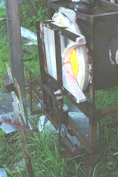
 This door is from Tom Ash and is reduced version from here: http://www.handmade-glass.com/ta_ghole.html The door is pneumatically operated and held snuggly against the flat panel front by track location and guide pin at the top.  The hole inside is actually square so the flat panel is being a mask and a lip.  The door edge is a parabola.  The device to the left is a pipe heater with an opening into the hole that shows in another picture on the page and the bar rests the irons in midair with drip falling away.  Insulation guards the strap.  The door completely closes the opening so pressure relief for hot gases is provided by the pipe heater opening to prevent/reduce back pressure into the burner head and body. 2008-05-07 Tom Ash glory hole door with part of pneumatic mechanism showling.
These two glory holes were photographed at Zero Gravity Glass near Austin Texas in 1998.  Other than size, the mechanisms are similar.  The doors are simple split doors with a default small hole in the middle.  When more space is needed the doors are opened as necessary up to the full size of either glory hole.  The picture below shows a detail of mechanism described below which allows the owner to work alone. Zero Gravity Hot wall- glory holes
The piping associated with the elbow in the middle top of the picture is the handle extending to the front for working alone.  The squarish bar bar below the elbow is connected to smaller rod links. Moving the handle from the right side to the left pushes the doors apart (a double link to move the left door is hidden behind the wheel below one of the links.)  The wheels shown are probably pulleys used on the cables for counter balance springs of garage doors which have ball bearings and are available at many hardware stores as door replacement parts.. 2006-05-30 Zero Gravity glory holes, split sliding, detail
This door on a furnace at the old Hickory Street Hot Glass (now disbanded) shows a simple common arrangement with a wheel on a rail at the top.  The chief disadvantage is that the wheel lives in the heat rising off the door, probably requiring higher temp materials (not bronze bushings) and graphite lubrication to keep it from corroding and freezing.  Advantages include total lack of anything below the door to be messed up if glass drains or drips coming out on second and further gathers. 2006-05-30 Hickory Street Hot Glass furnace, rolling hanging door
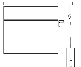
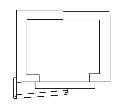
This sketch shows the top view of a door seen somewhere forgotten.  The advantage is that the mount does not have to be adjustable or precisely placed to move flush against the furnace face, thus giving a good heat seal.  It does require two sets of aligned bearings instead of one and the door only works if vertical. 2006-05-30
 One furnace door I saw and haven't found a picture yet used a long bent tube that pivoted off the back left corner of the furnace and arched over to hold the door, the whole swinging the side, yet keeping the hot face of the door away from the glass blower.
Furnace, top section, door double pivot, drawing
This massive set of doors is on a glory hole at the Tacoma Glass Museum.  The outer frame rolls apart on the rails at the top, splitting all the doors apart for full access to the huge round opening. Each of the pairs of the doors is hinged, opened by placing a loop (or hook) over the pins sticking up near the center line. The odd center hole somewhat reduces the heat escaping while giving more clearance if only the smallest left hand door is opened. 2006-05-30 Tacoma Glass Museum, huge glory hole, multiple inset, split hinged doors
Hands On Glass, Hot wall, pneumatic gloryhole rings Hot wall at Hands On Glass, Corning NY.  Note the stacked doors multi-sided glory hole and the simplicity of the rectangular door of the furnace.  The glory hole doors are pneumatically lifted to the side, leaving a round hole behind each one.
Bowling Green Gloryhole door pneumatic right, door in door left, rolling furnace door Bowling Green State U @1993 At Bowling Green State U in 1993, the gloryhole door to the right is a balanced pair that are hung on a chain and moved via a pneumatic cylinder producing a variable sized diamond shaped opening until nearly fully open when the square inside is exposed.  It is built of fire brick. 
The smaller glory hole to the left, a dull red in this picture, is a door-in-door hinged. 
The furnace in the middle has a rolling door in a fairly unusual arrangement with the door at a slope, running wheels on the bottom and guide wheels at the top. 2006-05-30

Annealers

Annealer doors are often metal shells stuffed with frax blanket although those for casting annealers where the mold is heated to casting temps may be insulating fire brick or castable.  The problem with all annealer is getting the door out of the way for access, which requires counterbalancing if the door opens up and strong hinges and hinge post framing if it swings. 

Tacoma Glass Museum - stacked front loading and 3 door top loading annealers. Commercial quality annealers

Corning Studio, large horizontal doors on annealers down front, smaller upright front opening annealers against back wall.  Annealers, office and Bill Gudenrath's bench
Bowling Green State University, heavy annealers used by students for casting as well as blown work.  Note heavy frames. Counterweight cables are barely visible.  Flames on door of front opening smaller annealers warn students that thinly insulated doors are hot to touch.

With cable counterweight, the pull of the weight is uniform, but the angle changes.  Normally the lid requires a fairly heavy hand lift to start, pulls swiftly past center, speeding up. The lid sits fairly tightly on the seal.  If springs were used, they would provide the greatest pull when the lid was closed, easing lift, but perhaps being too light to seal.

BGSU annealers in a row
Pilchuck Glass School annealers, which are set out from the wall behind them so the weights can descend.  The frames carrying the pulleys below the low ceiling are attached to the frame of the annealer, moving with it..

Pilchuck hot floor with annealers in background

Note the angle of the wires, actually going to a pulley over the lid then back further and down to the weight behind the lid.  This gives a better lift. (drawing below)

Pilchuck annealers with cable lifts offset to middle

Annealer with counterweight cable lift shifted toward middle Annealer with counter weight to rear on pulley
An alternative to the cable counterweight hangs a weight off the back of the annealer with a line just long enough that it sits on the floor when fully open.  The long eyebolt brings the hanging point back under the thick lid as it opens so the weight trying to open the lid decreases as the center of gravity gets closer to the pivot point.  The door can (almost) be parked in any location.  There is no hinge - the door rests on a small shelf when open and can be lifted off when the counterweight is unhooked taking care because there is an element on the lid face fed by a cable at one end. Annealler side view showing back shelf vs hinge and counter weight


Back to Equipment Sequence

Contact Mike Firth