Controllers
and Controlling Electric Power

Rev. ... 2002-11-04, 2003-02-23, -10-10, -10-18, 2004-07-27
2005-04-21, -05-10, -07-01, -12-16, 2008-04-10, -12-09, 2009-05-27, 2012-10-18
[Search on date pattern to find latest changes, more than one may be found.]

Return to Sitemap
Back to Equipment Sequence

Local Links on this Page

Introduction

Choices & History

Variac

Mercury Displacement Relay

DIGITRY

SSR, SCR

AD595

Phase Control

RELAY

Power Control on Cables

CONTROLLER COMPARISON

Electrical Heat Elements

Related Pages

Gas Control & Ignition

Thermocouples & RTDs

Sources of commercial controllers

Electricity for Glassblowers


   The purpose of a controller is to regulate the temperature of a heating device either at a fixed point or as a controlled ramping change from one temperature to another over minutes or hours. Most glass studios have several controllers for the heat supplied to annealers, color kilns, and furnaces and these may be combined in one electronic unit or be separated. A controller may include safety features required by either the electrical code (NEC) or one of several fire codes and thus cost more.
  Most controllers these days use solid state electronics in both the box that sets the temperature and in the device that actually throttles the electricity, which are connected by wires.  With solid state control, small amounts of electrons injected into the device permit large amounts of power to flow and this can be very finely tuned. Solid state boxes allow programming ramps up and down in sequence for special tasks.
   Alternatives to solid state controllers include carbon rheostats which add resistance to the circuit, variable transformers which change the output voltage and saturable reactors which interfere with current flow (?).  The first wastes power and generates a lot of heat while the second is limited in power and is costly in larger sizes and both would need a motor drive to control remotely.
   The pieces usually found in a system include the controller, a thermocouple to measure temperature, a heat source (gas or electric elements), and the interface to take the weak signals from the controller and apply them to the heat source. Schematic  It is my philosophy to match the capacity of the interface to the demands of the heat source and locate it near the source and to locate the control function in a convenient location.  This means short heavy wires carry power to the heat source and longer light weight wires carry the thermocouple signal and control signal from the heated item to the controller.  The most common alternatives to this are to put all the functions in one box located near the heated item - done with ceramic kilns - and to mount several heavy duty interfaces near the main power supply for the building with controllers grouped elsewhere - this being especially done with mercury contactors requiring rigid positioning.  Controllers and SSR's are sensitive to overheating and must be located with that in mind. 2005-12-16
   Controllers are now made with advanced features in a small box for under $150, or with a single display and key pad for 5 devices, or with computer control with history and plan on the computer screen.  Either electric heating or gas burning can be controlled, the latter involving considerably more complicated and costly safety features. Gas Control & Ignition
  Most of the discussion on this page is related to heating, annealing, sagging, and fusing glass.  Melting glass for blowing using controllers is beyond my experience and requires special elements and special power supplies.

Among features that may be important for particular purposes are
Choice of action at the end of the ramp - shut down or hold
Choice of what happens if temp is not reached at end of ramp, wait until reached or quit at achieved temp
Multiple choices of sequences of ramps (programs) stored  to avoid reentry
Stitching program sequences  to make longer sequences
Controlling a sequence like ramp over 3 hours to 900F, hold 30 min. to soak, rise quickly to 1300F, soak 10 minutes, cool quickly to 900F, soak 1 hr, ramp down over 8 hours to 650F, shut down.


Choices (and history) in Temperature Controllers for Glass By Mike Firth

Rev. 3/13/97, 2/18/98, 2000-8-20

Controlling temperature for melting glass and annealing it has used a number of devices historically and has seen great improvement in the last few years. Electric melt and annealing control is relatively easy, but limited in quantity and maximum temperature; while adding control to gas furnaces jumps the cost. One ongoing problem is the need to accurately control the fall of temperature in the annealer over many hours.

Temperature control can take two forms, open loop and closed loop. In an open loop, a device controls the heater, thus raising or lowering the temperature, but the temperature does not affect the device. In a closed loop, the measurement of the temperature modifies the behavior of the device in controlling the heat. A resistance control, dimmer or Variac (variable transformer) is open loop; modern controllers are closed loop.

To quickly summarize the following, open loop devices were first used, then as microcomputer technology began in the 70's, fairly expensive controllers that used closed loops were available. Then the cost started coming down and a series of multi-step keypad programmed controllers, such as Digitry, came on the market. Most recently, controllers that "learn" the characteristics of the furnace or annealer and adapt for better control have come on the market. Some of these have computer ports so that control can be maintained on a computer screen. And now we are seeing multiple ramping units at relatively low cost (under $200.)

In glass working, the chief open loop devices have been the food cooking oven controller, variations on dimmers, and the variable transformer (Variac, a brand name.)  In each case, if a roughly constant temperature is wanted, the human adjusts a knob until it is about right. Most retail dimmers do not have anything like enough capacity to control an annealer; but a dimmer can control a heavier triac or it is not difficult to build a 25 amp dimmer (or bigger.)*  Oven controls used are variable resistors, like on home ovens, which are easily available and have the capacity but waste energy and are not very sensitive.

Harvey Littleton's Variac Based Controller from the 60's The Variac has a venerable history in modern glass blowing because at the time the modern art movement started, there were a lot of large capacity Variacs available as military surplus and triacs and electronic dimmers did not yet exist. A Variac is two coils of wire, looking somewhat like a motor with a knob on the shaft, which is adjusted to change the voltage from 0 to maximum available. They are efficient. They are also heavy and if not available surplus they are also expensive and have a limited capacity. Variacs are important because early in the history of modern glassblowing, they allowed annealing to take place over many hours when hand control would be impossible because they were built into a open loop automatic control as follows.

The Variac was mounted on a board with a 24 hour timer whose purpose was to provide a very slow motor. On the shafts of the timer and transformer were mounted disks or segments around which string was run from one to the other. As the timer dial turned, the Variac dial was dragged along, slowly lowering the voltage. Some people used cam shaped disks, so the Variac moved more slowly during the first hours and faster during the later ones. Some of these are still in use, I saw one at John Littleton and Kate Vogel's studio in 1995. As the voltage fell, the power fell as the square of the change and the temperature fell accordingly. But the temperature curve was only monitored by a human and did not affect the timing of the process. (Image shows Harvey Littleton's Variac controller from his book.)

Recently, exactly the same thing can and has been done for a few dollars and it is one better than Variac. Peet Robison in New Mexico built a controller in which comparator chip compared the amplified voltage from a thermocouple to the output from an digital to analog converter (DAC) turning on a triac controlling the heating element when the thermo voltage was lower than the DAC. The DAC setting was controlled by a small counter that changed every few minutes. The total parts cost is about $8 for building this. Note that it is closed loop, because the temperature reading influences the comparator, but what is being controlled is some arbitrary number not a precise temperature. Also the temperature curve is straight line, which is an improvement, but not the best. Today, for $12.50, a chip is available which corrects for oddities of a K-type thermocouple, so the output is (within a small percentage) a voltage the same as the temperature (6.55 volts = 655.C) and thus finer control is possible.

DIGITRY - The most widely used controller in glass
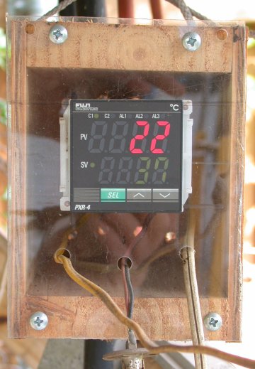
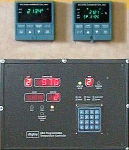
 melting and annealing is probablyDigitry and commercial controllers at Jim Bowman's shop the Digitry GB4 [lower in image] which has now been succeeded by the GB5 in 2005.  These control up to 5 units which costs $1465 for the basic unit plus about $55 per kiln or annealer for thermocouple and additional solid state relay or contactor. The GB1 controls one device and costs about $550 + kiln add-ons. The Digitry is convenient to use, providing specific keys on a keypad to select the device and numeric keys to enter device numbers, temperatures and hours. It allows multi-step programs, so an annealer can be set to hold a temperature for 2 hours, then take an hour to drop 50 degrees, then take an hour to drop 150 degrees, and so forth. The cost per unit controlled is not as high as a dedicated commercial controller (which may run $1500-2000), but is still irritatingly high, especially if less than 5 units are controlled. And there is the problem that if a single controller goes down, the shop is down. Similar units are made by other companies, including Paragon
Exact features of the GB5 for comparison include: Scanning display through 5 devices, large LED display, 15 set points per device, programming to 500 hours per step (as in annealing castings), 4 extra profiles can be stored, retains profiles during power failure, set delayed schedule for off peak rates, audio alarms, skip steps if needed (in fusing usually), optional power sharing between units, PC connectivity, and 4-20 ma control.

Two new technologies are available for control. One is a self contained unit that will provide a single or multiple ramp and learn the characteristics to the controlled unit. [These can look like the two upper units in the image.] The other is using a computer to control the controller. Actually, the first units can be had with an option that allows computer control of changing the ramp and then letting the unit run.

Several companies have come to market with small (2" x 2" x 4") controllers for about $200 that avoid a complication that has plagued controllers for years. PID (Proportional-Integral-Derivative) is a method that allows programming controllers so they do not overshoot their goal or over-control, wasting energy. Unfortunately, PID requires careful selection of parameters to match the furnace/annealer to the heat source. This is eliminated in the new units because they "learn" the characteristics of the equipment, adapting to different building temperatures, etc. I have an annealer with a low wattage light bulb across the elements that goes on and off with the elements. It is easy and fun to watch as the controller turns on the element and, after the temperature has risen, turns it off to see how much coasting goes on. After testing, the unit finally runs the temperature right up to the setting.

A $300 solution involves buying a CN76000 Auto-Tune Controller (dc pulse output with alarm option, CN76120, $195 or adding remote setpoint option, CN76120-SP, $234, page P-95) from Omega (1-888-TC- OMEGA, ask for the Temperature Handbook, www.tcomega.com ), along with a K-type thermocouple, DH-1-8-K-12, $19, (page A-13), 25 feet of K type thermocouple wire, PR-K-24, $15, male and female K-type miniature plug connectors (SMP-K-MF $4, page G-16) and a Solid State Relay SSR240DC25 (DC control voltage, 25 amps, up to 280 Volt) $26 + Heat Sink FHS-2, $17. There are only 3 pairs of wires to hook up - AC power, thermocouple, output. [Controller Comparison]

AD595 - There is a set of Analog Devices chips that will take a K-type thermocouple and produce a 10 mv reading per degree C or produce a setpoint controller. With a fairly simple switch, a single chip can do either. I paid $12.50 a chip (buying 2 to meet $25 minimum from Newark Electronics, current suggested retail for quantity 100 is $7.28. Data Sheet PDF on 2012-10-18

AD595

AD597

Drawing of 595 14 pin integrated circuit chip

Drawing of 597 8 pin integrated circuit chip

Drawings copyright 1999 Analog Devices data sheet used under fair use copyright law link.

The two chips shown above are designed to have a K-type connected to the pins at one end (pins 1 and 14/8). For the reasons given in the discussion of thermocouple connections, AD recommends making heavy copper connections to these two pins showing wide foil connections on their PCB layout. I used a wire wrap socket and bent the pins over to make the solder connection rather than use smaller wire. All this is to keep the connections as close to the chip temperature (which is measured by ICE POINT COMP) as possible. I solder a short length of thermocouple connection wire to the PCB and put a mini-connector on the end of that.

Circuit to be tested and posted soon. (he said on 9/20/2000)

1 chip Controller board schematicThis is the circuit for using the AD595. As shown in the diagram, a DPDT switch allows choosing between measuring temperature and checking the set point. A digital volt meter connected to TP (Test Point) and ground (GND) will show 0.001 volts per degree Centigrade (1 mv/C) I use a multi-turn potentiometer. A limitation of the chip is that it will only drive 5 ma. There are opto-isolators that will work with that drive level, but only just barely. So gates are added and the easiest to get are inverting. Although hard to see, the three gates are Schmidt Trigger inverting gates (3 of 6 in a 74H14) because the signal changes slowly and CMOS usually doesn't like slowly changing signals. [2002-10-26 I had kind of let this circuit lay around for a while, but got bugged and today realized I might need a pull-up resistor.  When I began looking for specs, I was dismayed to find that the 74HCT14 from Radio Shack are very limited on voltage range because they are to work with TTL. So my whole reason for choosing CMOS - voltage variability - is voided because I didn't know/look at the specs.  Now to find one cheap/quick.] 
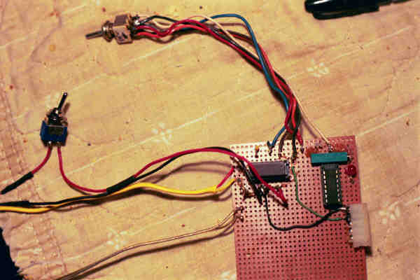
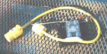
2002-11-04 I got the thing working, after redrawing the schematic from the bottom and tracing all the wires. There was not a good connection at the measuring point.  The core problem was that the measuring points were not connected reliably.  I tore off the wires and removed the Molex.  Finding nothing smaller, I used two terminals of a European style terminal strip.  Once firmly connected, it seems to work well at light bulb temps.  Will test with one of my boxes when it isn't raining and I am awake.


This is the layout of my small unit. The AD595 chip is in the highlighted area upper left corner, the multi-turn pot is the green box to the upper right and the CMOS chip is below that. The switch to the left is the 9 volt power on/off and the thermocouple wires are below that. The switch above chooses between measuring the temp or the set point. The short white Molex strip on the right edge is for plugging in meter probes to measure set point or temp.
The AD595 chip is in a wire wrap socket so the heavy pins make the connection the same temp which the chip compensates for.
circuit board for controller
The is the PCB (printed circuit board) layout suggested by Analog Devices - note the heavier wiring from 1 & 14 to the thermocouple wires for temp compensation. AD495 Printed circuit board layout from Analog Devices


Power control - Relays

The three basic ways of controlling a bunch of power (30-100 amps, 1 or 3 phase power) are a contactor, a MDR or an SSR. All of these are relays and a relay is a device for switching on and off power in one circuit with another circuit, which may be of a different voltage, for convenience.

A mechanical relay consists of a coil (a winding of copper wire) that creates a magnetic field in a iron core that attracts the iron plate that carries the contacts that switch the power. While relays may take dozens of forms, contactors are a special form that has only normally open contacts that are pulled shut with the magnetic field. The disadvantages of contactors are that they are normally noisy, clanking with each open/shut cycle, may produce electrical noise from the arc, and they cannot be switched more often than every couple of seconds. A major advantage of contactors is that power is completely off when they are open, no leakage, so they are used to kill circuits ahead of SSR's, etc.. A contact may throw an arc on closing or opening. Contactor

"Mercury Displacement Relay (MDR) - An electromechanical switching device having one or more poles that contain metallic mercury and a plunger which, when energized by a magnetic field, moves into a pool of mercury, displacing the mercury sufficiently to create a closed electrical circuit." For this definition and safety steps go to Disposal of Mercury Displacement Relays - Watlow Electric Manufacturing Company

The main advantage of an MDR over a contactor is silence although it can also be cycled faster than a contactor. A big disadvantage is disposal and risk if mercury escapes, which is unlikely but critical because mercury vapor is poisonous and the spill must be treated as hazardous.  A nuisance is that the MDR must be mounted in a specific position to work, which may complicate a portable rig (which must then not be operated on its back, only upright.)

SSR is a solid state relay, discussed more below. The advantage of an SSR is that is can be cycled very rapidly (60-120 times per second if needed). The disadvantages are that a small amount of current leaks through the SSR to the element, even when it is off, and when it fails, it is more likely to fail on (short) than off (open.) Also, an SSR, SCR, or Triac must be provided with a serious heat sink and good air flow. It should not be enclosed inside a box.

From: <JWalsh2000@aol.com>
Subject: Your SSR and Control web page
Date: Monday, October 15, 2001 1:18 PM
A few additional items:
You can use a mechanical, mercury or solid state relay (SSR) to activate the heater in your kiln. A mechanical relay has a recommended cycle time (on time plus off time) of more than 60 seconds and usually about 1 million mechanical cycles. A mercury contactor has a recommendation of 10 second cycle time and 3-8 million cycles (a couple of years). A SSR has a cycle time of less than one second and a virtually unlimited life. The long cycle times required in the mechanical or mercury devices means that your heater will experience thermal stress and will fail sooner than when used with a SSR product. That failure is frequently around the heater's connection due to the thermal expansion and contraction that occurs when the heater in "on" for many seconds and then "off" for many seconds. The shorter that you can keep these "on" bursts and the "off" burst, the longer the heater will last.

Therefore a SSR is an ideal device to control electric heaters. The biggest concern with SSRs is that they generate a little heat that will destroy the SSR if you do not remove that heat. You can view the math at: http://www.ciicontrols.com/library/ssr/heatcalculations.htm
As long as you use a quality SSR and mount it on a heatsink, it should have an incredibly long life.

Regards;
John Walsh, General Manager
Continental Industries International (We make temperature controls and SSRs.)

Phase Control

: I'm not an electronic engineer or even close, but my understanding is that
: SCR's are the most sophisticated switch available. A mercury switch turns
: on and off every few seconds. An SCR turns on or off 120 times a second.
: This allows for proportional control. (which lessens the overshoot factor)
: It can also be adjusted relative to bias and gain, which can limit the
: amount of current it draws. For instance I have an element that, due to
: it's being shortened, draws 2 amps more than the breaker will allow. On
: full gain it will pop the breaker, with the gain turned back it doesn't. I
: don't understand the difference between SSR's etc, but I think the SSR is
: less sophisticated and cheaper. It may indeed do a very good job of
: switching a kiln.
: Bert

"An SCR (Silicon Control Rectifier) is (without going into great detail) an electronic switch. It is either off or on, but you can delay when it is turned on in relation to the alternating current's cycle. If you turn it on early in the cycle, you get near full power. If you turn it on near the end of the cycle, you get very little power. Once turned on, it will stay on for the rest of the cycle. You can turn it on with vary little power, i.e. a few milliamps to the gate (control element) will allow you to "switch on" many amps (usually the full 15Amp circuit).
With this technique you can build a fairly well regulated power supply that will support regulated power to heaters, lights, etc. The only down side to a controller like this is that it creates a lot of electrical noise, and may drive radios in the area nuts."
samg (Sam Gaylord)

Since I have built the things from scratch (but not melted the silicon) I suppose I am qualified to offer a few definitions.

An SCR (Silicon Control Rectifier) is a device that rectifies current (changes it from AC to DC) which can be turned on with a small current. If used alone with AC, it produces pulses of 1/2 the AC power when on. Therefore, when SCR's are used, they are almost always used in pairs to pass both halves of the AC power.

A triac is effectively two SCR's built on one small piece of silicon with one wire controlling them. The two can't used separately. It is a triac that is used in dimmers and small motor speed controls.


  The charts at the right show how phase control works. The sweeping curve (mostly in red in the upper image) is the voltage (or amperage) sine wave for 120 volt AC power.  It goes from maximum thru zero to the minimum back thru zero to maximum 60 times a second in the U.S. Each hump from zero crossing to zero crossing is a half cycle - 120 of them a second.
  Phase control involves turning on an SCR pair or a triac some time later in the half cycle than at zero. [It turns off at each zero crossing.]  This has good points and bad points.  The biggest bad point is that the sharp rise of the voltage from zero, shown by the vertical green lines in both images, will produce Radio Frequency Interference (RFI) with other electronic devices. 
AC cycles showing late phase turn on (green)
The best good point is that phase allows very fine control of the power. While a zero crossing turn on signal allows cutting the power to one half cycle now and another half cycle later, this means the element has time to cool before reheating, which may cause strain on the element.  With phase control power can be cut back very evenly and minutely.  Even if a simple relationship is desired, say 1/120th power, instead of one half cycle each second, the power could be turned on late in every half cycle so that every cycle produces 1/120th of maximum power - much smoother.
  In the upper image, power jumps from zero up to the curve (the green line) late in the half cycle and well after the maximum and the area between the green line and the zero line is small - not much power.  In the lower image, the jump occurs shortly after the zero crossing, the area between the green curve and zero line is much greater - lots of power.
AC Cycles showing early phase turn on (green)
How is phase control carried out?  In a manual circuit a variable resister controls charging of a capacitor and the voltage on the capacitor triggers the SCR/triac a specific time after zero each time.   In a pure microcomputer circuit, it is possible to literally sense the zero crossing, count microseconds and pulse the SCR/triac at the right time.
  A more common control method is to apply a voltage that produces the same result as the resister/capacitor delay, a voltage produced by a digital to analog converter or a 4ma-20ma current converter. 
Because of the sharpness of the point of the voltage change late in the half cycle, rising then immediately falling, the RFI is typically greater then.


An SSR (Solid State Relay) is a combination of a Zero Crossing Switch and a Triac/SCR. One of the problems of phase control it that it can produce electronic noise and some devices will overheat or otherwise be damaged by the different shape of the power (from a smooth sine wave.) If the SCR turn-on signal is applied at the time of the zero power crossing, then the output will be an AC half-cycle.  Then instead of phase controlling each cycle, power is on or off for complete half cycles and power may be controlled to the nearest 120th of a second.

Why then use SCR's instead of Triacs or SSR's? Well, for higher voltage, higher current, and 3 phase power.   Triacs will break down at higher voltages, have limited amperage available and don't offer the needed control. And for motors a curious thing happens: a motor shifts the phase relationship of current and voltage so the Triac thinks the power has never shut off, so it stays on. SCR's allow specific circuitry to deal with 3 phase power and the phase shifts.


Solid state relay mounted in cableThe image at right shows the way I currently control power.  A 12 gauge wire has been cut open and the power wire (black) cut neatly and the ends stripped.  These were attached to the load screws of a commercial SSR and the area sealed with 100% silicone sealant.  A snap on plastic cover is provided with the relay.  The connectors in this case are 15 amp standard plugs of a type I like to use because the wire goes straight in to the internal screws.  The control is thin stranded speaker wire connected to a phono plug common to my various controllers.  The black area inside the loop of wire is the heat sink, not well shown in this image. 2005-04-21
SSR cable controlled by 120 voltTo the right is a second power control cable built the same way as the one above, except that the SSR is controlled by 120  VAC like the one below instead of 5 VDC.  So the cord from the control terminals ends in a common 120 plug instead of phono plug.  I use this to control a second element in my annealer when I want to take it up to 1450F or so instead of no higher than 1100F.  The main element is on the lid and the second is the original hung around the top of the sides, which is actually broken and just hooked together.  There is a low wattage standard light bulb indicating power on for the main element.  Unscrewing this bulb and adding a common socket adaptor lets me plug in this control to a second power source (an extension cord when I need it) rather than rewiring to handle 20+ amps that both circuits would pull together.
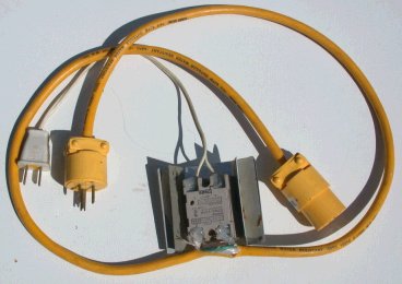
 2005-05-10
 

The montage at right shows the construction of a 220* volt SSR mounted on a 30 amp dryer cord and outlet.  The upper image shows the side view of the outlet, cord, and heat sink 220 Solid state relay SSR mounted on dryer cord.
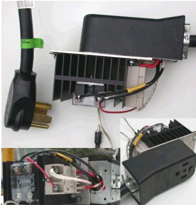
as well as the edge view of the adaptor mounting plate.  The lower right image shows the face of the surface mount outlet and a different view of the plate, while the lower left shows the two solid state relays and the wiring coming out of the outlet.  I use RCA phono plugs to plug in the 5 vdc controls and this is shown in the middle with the wire leading to the relay.
It is cheaper to use standard household cords and outlets instead of more specialized ones like twistlock.  Until 1999, dryer and range cords could have only 3 prongs, an exception to the general terms of the wiring code allowing the third wire to be both neutral and safety ground.  The exception was dropped with the 1999 version of the code and all dryers and ranges delivered since then have had 4 prongs and all new construction has 4 prong outlets.  People moving older equipment into new construction have to change off the cables as do those buying new equipment for an older residence.  Eventually, the old buildings will have to be rewired.
The four wires are the two main power carrying wires, one red and one black, referenced 120 volts* away from the white neutral and a green safety ground.  Because of phase, the red and the black reference 240 volts* to each other.  For a heating element connected only to power interrupting either wire will shut down the circuit.  The other is still hot with respect to neutral and ground.
Neutral is a power line that can be used for return on a 120 volt circuit.  Ground is a safety wire which is connected to the chassis, so if one of the hot wires touches the chassis, instead of leaving it hot, it will fire the circuit breaker.
The plug and outlet shown have an L shaped profile prong for safety ground which a 30 amp outlet must have.  A 50 amp range cord has a flat blade here in line with the side blades.  Loose plugs (not molded) come with both prongs and the correct one is used for the connection.

CONSTRUCTION
To make a rigid mount, a 3x6x1/8" aluminum plate was drilled and countersunk to match the four holes at the ends of the heat sink and four to match existing mounting holes in the back of the outlet.
Referring to the lower left image, coming out of the hole are a pair of red wires, a pair of black and a white.  The larger wires in the center, one red and one black are the ends of the molded 30 amp dryer cord.  The red is attached directly to the beige colored SSR and a return wire from the other terminal, white wire painted red, carries the power back in to one terminal of the outlet.  The black wire has an extension via yellow crimp on connector to the black SSR on the left and the solid colored black wire is the return to the outlet.  The thin red wire is a jumper from the black SSR output to the beige SSR input.  The white wire is a jumper to the neutral in the outlet.  The two SSR's are obviously different in their control - the black one uses 5 vdc to turn it on through the lower terminals in the picture, while the beige one uses 120 AC power input to control 120 to 220 AC output.  Tapping the output of the one to control the other means both sides of the line are turned on and off together.
After the picture was taken, metal tape was applied over the hole. 2005-05-01

* Voltages are nominal.
 

Pictures of Mike Firth's SSRThe images at right show a solid state relay that I built at a time when more time than money was available and when SSR's cost more than they do now.  Almost all the part came from a hardware store or Radio Shack.  At one end of the metal box is a snap in grounded outlet.  At the other end is bolted the triac with a heat sink outside.  This proved inadequate in the Texas heat, so sheet aluminum was pop riveted to the top and bottom, with heat sink compound on all.  The cord from an air conditioner extension enters though a cable clamp.  Inside the box, a terminal strip holds capacitor and resistor and a small circuit board holds the zero crossing opto-isolator Triac driver chip.
SSR using zero crossing triggeringIn the schematic at right, taken from Teccor application notes* is likely the one I used for building the box above.  A low value resister (22 ohms) limits current flow between the triac and chip and 100 Ohm resister and 0.1 microfarad capacitor provide snubbing protection against small inductance spikes.


Cautions about SSR's, Triacs, and SCR's? None of these turn off completely, there is a small leakage current. For safe work, there must be a mechanical switch, manual, relay or contactor to completely break the circuit. Further, if these devices get overheated, they can fail ON and the only way to break the circuit is mechanically - a circuit breaker switch or contactor. In an annealer, failing ON means the glass gets overheated and sags.

So if a contactor is needed anyway, why not just use that for power control? Well, contactors produce sparks and interference of their own and mechanical contactors are audibly noisy (while mercury contactors are not) and the life of contactor is shortened considerably if it is turned on and off as often as an SSR commonly is - a controller must be told to operate less often with a contactor.

* [Previously, Teccor had a neat file with individual notes, now there is a large file   http://www.littelfuse.com/data/Product_Catalogs/PowerThyristorApplicationNotes.pdf ]

Melody wrote:

holly kehler wrote:
>
> I purchased my Fuji PXV3 controller in April last year. It's
> wonderful not to have to baby-sit those switches in my Evenheat
> top + side-fired kiln to maintain temperature! I slump, fuse +
> anneal. Cost was less than $ 200, including thermocouple and
> solid state relay; 4 ramp soak steps possible; if I need more
> steps I manually reprogram.

I checked out the specs on this & the details look good. However, I showed this to my husband (engineer) & a friend (ceramic artist) and they both posed the question "Well, how would you plug it in?"
I have no answer. And, looking at it, is it even possible to use this on a ceramic kiln?
I am completely ignorant about this and really want to start doing glass in my kiln but need the temperature controller. I LOVE the price on this one, of course, but will it work?
Can anyone recommend a specific controller for me? I have no *earthly* idea what to get or who to even ask about it besides you guys.
Thanks much!
Melody

The small fractional DIN controllers have screw terminals on the back that require a minimum of 3 pair of connections: AC power, thermocouple, and power control. Power control depends on choices made when buying the controller. I buy solid state relays (SSR) and buy the matching DC output option. On a solid state relay, the terminals are Control and Load.
For the lower level loads (under 15 amps) I take an air conditioner extension cord, cut the hot lead and wire it to the load. For a kiln with an existing plug, it would be easiest to buy a matching plug and outlet and a short length of heavy power cord. (If the plug matches a dryer (30A) or range (50A) then a cord with a molded on plug could be purchased.) I would mount the outlet in a standard surface mount electrical box, put that on a board with the SSR and run short wires into the box.
Attach the control wires to the SSR, plug in the controller, plug in the power cord, plug in the kiln, slide the thermocouple into place and go. If this is confusing, get someone who knows a bit more about electricity to help.

The drawing below shows the relationships of a simple connection to a kiln or annealer. The controller has three pairs of connections: 1) its own power, usually 120 volts AC, 2) A thermocouple, inserted in the kiln, usually K-type for glass work, connected by proper wires if extended, 3) Signal (low voltage) connections to the SSR.
The SSR (Solid State Relay) has two sets of connections, 1) low level control signals,  2) Power Connection which interrupts the power supply to the element.

Circuit showing kiln element connection.

 ----- Original Message ----- From: "Trask Family" <traskfamily@columbus.rr.com> To: <thetrasks@bigfoot.com> Sent: Saturday, March 23, 2002 8:13 AM Subject: controller
> Hey Mike,
>
> Love your articles!!
>
> Took a class a few weeks ago and I'm setting up a flameworking lab in my
> basement!
   This is not my area of expertise, but be sure you have fire resistant material in the path of the flame - it can carry heat several feet.  Cement board (used behind tile in bathrooms) has been mentioned
> Noticed your reference to the controller in articles 16 & 17.
>
> I called Love-Controls and they are now selling a model 32A for $163 with 16
> segment programmable ramp/soak times. Or a larger similar feature set 16A for
> 194
>
> In #18 you mentioned the need for a 4 set-point option (another $50).  Why
> would you need the 4 set point option?    
  Changing the temperatures with few button controllers is a nuisance, but a 16 segment controller might help.  When changing the temp, you hold down the up or down arrows.  The temp starts to change, 1 degree at a time about 2 times per second.  After a while it speeds up, changing 10-20 degrees per second.  Then after a while longer, the hundreds start changing.   So you play a game of touching the temp, then letting go before it speeds up too much and over shooting.  If I am moving 300 F, like when I go from holding at the annealing point (890 for my glass) to the strain point (650F), I would frequently get into the 100's, so I had to come up from 500 and it bugged me.  the 4 set point lets you have 4 different set points (adjustable) and use 2 switches to select between them.  I cannot recommend for convenience the Love unit, as I bought it,.  The point in the command sequence that turns on programmable ramping is BEFORE the time of ramp and hold/off choice entries, and there is no way to back up, so you have to go through all commands twice, once for settings and then back again to turn it on.    I am strongly considering the Fuji controllers for next time.  Among other features (including 2 8 point ramp soak profiles that can be linked) one of the things you can do is put your favorite commands at the start of the list and hide commands you don't use.  The manual is online in a pdf file if you are interested. http://www.fujicontrols.com/ [2008-04-10 I purchased a Fuji PXR controller and find it very satisfactory for fusing and annealing. The commands are arranged in 3 groups and 2 sets of settings may be kept in memory.  The command for ramping is the first in the first group, sharply reducing keystrokes.]
>
> -------------------------
> You also mentioned needing solid-state relay at $15 plus.  These were $100+
> (as per phone conversation with sales rep Bill German).  He did mention
> however that I could get a Mercury contactor for $18 and would need a snubber
> for $3.50.  I would need a solid state output rather that the 5v pulsed
> output that would drive the solid-state relay.
>
> Did you have a solid-state relay that wasn't in mind the high bucks. Or have
> things changes alot?
      I consider his price for a solid state relay to be wildly high and for the mercury contactor to be wildly low.  The price in the article is now too low.  Omega (www.tcomega.com ) has 25 Amp dc control signal SSR's for $26 (SSR240DC25) with mid-quality heat sink ( FHS-2  1.2°C rise/Watt) for $17.  Their 45 amp SSR using the same heat sink is still only $47 total and in a different line 50 amp is $53 with the best heat sink (yes, you need one) being $21.)   Omega prices single pole mercury displacement relays at $34 for 35 amps (MDR120-1035) and $53 for 60 amps (MDR120-1-60) these having 120 volt coils.  24 volt AC coils are no additional cost (change the 120 in the number to 24)   A mercury relay must be mounted in a specific upright position, while SSR's and mechanical relays may operate in any position, which is nice with my portable equipment.
>
> See web site www.love-controls.com.  Manuals are online.


Controller Comparison  [Under Construction as I try to make sense of units not owned.]

Love Controls 76000 --- The unit I have actually been using for several  years.
 Good points: Auto Tune, easy choices. Optional 4 set points, switch selected for quick changes.
 Poor points: Setting a change in temp if not already in at one of the set points. The choices for ramp time and behavior at end of ramp come after the Prog On/Off command and there is no way to back up.  One has to bypass the On/Off, make the entries, then go though all the 20 or more steps again to turn the programming on.

Fuji Micro-Controller X - Model: PXR
Fuji PXR controller mounted in wood box with plex face.
  The most attractive feature seems to be the low cost while offering ramp/soak segments.  Unit can be set to start ramp at power on. A mask feature allows hiding commands which are not needed/used.  [2008-04-10 I purchased a Fuji PXR controller and find it very satisfactory for fusing and annealing. The commands are arranged in 3 groups and 2 sets of settings may be kept in memory.  The command for ramping is the first in the first group, sharply reducing keystrokes.][2009-05-27 The image shows my mounting of this unit, which is about 2"(50mm) square on the face and 4"(100mm) deep. It is mounted in a Plexiglas panel screwed to a wood box with cords for AC power, SCR control, and thermocouple exiting the front from screw terminals on the back..  Full surround of the unit is provided because of problems with previous unit of similar size. The mount to the Plexiglas is a clamp between the front flange and an adjustable collar behind.   Four membrane buttons provide access, being pushed in single and two button combinations.  The two right buttons increase and decrease values or move through menu choices.  The blue-green SEL button acts like the Enter key on a computer keyboard.  This display shows a set point of 37C with a current temp of 22C.  Menu access is obtained by pushing the two left buttons.  Menu titles are presented on the red upper display in very abbreviated 4 character forms (see examples below) and values on the green lower.  Settings are held during power failure.]

Troubleshooting The FUJI Controller

The annealer is shipped with the following program.

Sv-1 - 950 (This is your first set value or the temp. that you want the kiln to go to.)
7n1r - 0.00 (This is your ramp rate to get to the first set value, 0.00 allows the kiln to go as fast as it can go. This value is in hours and minutes of ramp time.)
7n1S - 2.00 (This is the soak or hold time that the kiln will stay at set value 1.)

rainbow line 1

This segment of the program will do the following:
Bring the annealer's temperature to 950 degrees as fast as it can go (0.00) and hold at 950 for 2.00 hours.

Rainbow line 2

Watlow Series 96
 
This unit more obviously is set up for a permanent control.  The most interesting feature is a custom menu to which some of the commands (not all) can be placed for quicker access - avoiding the problems of clicking through the multiple choices.
The clearest evidence of permanent control is that choosing whether changes will be ramped or direct, is on the Global Menu of the Setup Page (2 changes of menu, 6 changes of page, 9 parameters down)  Ramp timing is set in degrees per sec or min not total time.
, Quick Menu Choices  Set Point 1, Auto-Tune Set Point, Auto Tune, Ramping Set Point,
 

Digitry GB1 & GB5-
Digitry and commercial controllers at Jim Bowman's shop  [Notes abovehttp://www.digitry.com/   [In the image at right, the lower half is the Digitry.] The GB5 is perhaps the most widely used unit in glass studios, even while being the subject of controversy.  Two points of debate are the concentration of all the control of the studio in one device - if it goes down, everything goes down - and the cost, which is about double the lowest cost units even if all parts of the unit are used.  The convenience of having a full numeric keypad is attractive.  "Ramps and soaks can occur in any combination. Each profile can have 15 steps of up to 99 hours each, allowing a total time of over 8 weeks. Plus, the GB1 can store 10 distinct profiles that can be instantly retrieved." On simpler units each temperature setting can be a ramp plus a soak, but two ramps requires losing a soak. [For example, on the Fuji, there are 8 set points that can be used as 2 sets of 4 but each setting ]
  Digitry pricing [2008-04-10] GB5 with 2 sending units $1465 with 3 sending units $1525 (4 & 5 possible), add $55 or more for SSR with heat sink and $45 for thermocouples. This makes it about $832.50 per unit for 2, $608.33 each for 3 ($427 for 5).  While this gives marvelous control for up to 5 units, most devices in the studio don't need ramping, etc.  A color oven is merely held at temp, as is a garage.  An annealer used only as that needs a simple ramp.  This compares with about $263 for a single unit Fiji with SSR & K-type. The GB1 costs about $650 per unit. http://www.digitry.com/price.html
 

Alternative Look
  How many key strokes and how messy to carry out the following operations:
 Bring annealer, empty, to 890F, as quickly as possible, and hold
 Bring annealer down from 890F, over 6 hours, to 600F and then drop to room temp.
 Bring annealer/kiln to 1000F ramping to avoid breaking glass.  Take temp quickly to 1300 for sag, drop to 900 for anneal.  (How hard to change temp manually over 300-500 range.)
 

Electrical Heat Elements
There are some really exotic ways of heating with electricity such as microwaves, direct injection of electricity, and arc, but most of these depend on melting most of the glass first so it becomes conductive and are complicated and dangerous to a user dipping a pipe into the glass.

So heating is normally done with an element.  This is a length of material that gets hot when electricity is run through it.  The natural resistance of materials that conduct electricity causes heating any time electricity flows.  In the normal use of wiring, every effort is made to reduce the heating by selecting materials with low resistance, most commonly copper and aluminum because of their cost, gold and silver being lower resistance but too costly for anything but contacts on switches.

The element material must first of all stand up to the heat.  While a thin aluminum film can be a heater in a warming tray, it will simply melt if taken to red heat.  A material that has been developed that remains strong enough when heated, Nichrome which is a nickel-chrome alloy with iron and aluminum added to some variations.  Wire: Nichrome (tm) & Other Resistance Alloys - Tech Data  The first problem with Nichrome and glass is that it gets very unhappy (ready to melt) at the temps that glass melts and thus produces a short life.

The nice thing about Nichrome and most other materials that might be used for heating is that their resistance goes up at they get hotter.  This means that if a certain voltage is applied, a certain amperage will flow when cold and as the element gets hotter, the amperage drops so at some point the heat output is limited and the element naturally stops getting hotter.

The smaller the wire diameter the higher the resistance and the longer the wire the higher the resistance. So the design of a heating element becomes a matter of varying the diameter of the wire against the length of the wire so the temperature of the wire gets hot enough, but not too hot, while putting enough power into the insulated box to raise the box temperature to the desired point.  Tables give the temperature of a straight wire of a certain size with certain amps.  Commonly, elements are coiled to get more wire into a given space and to increase the temperature because one coil raises the temperature of the next one.  A 1000 watt 120 volt heating element might be 3 feet long when coiled and pulled out to working length.

And exception to the resistance curve of the pure resistance elements are silicon carbide heating elements, which drop in resistance up to 1960F and molybdenum disilicide heating elements, which have very low resistance and require a hefty transformer to drop the voltage and increase the amps also the resistance changes considerably with age, requiring adjustment to deal with loss of heating if not adjusted. Both are rigid cast ceramic material and must be bought in the shape they will be used, a U shape being most common.    They are used because of the high temp limits.  "Molybdenum disilicide MD-31 for element temperatures up to 1700ºC (3100ºF) and MD-33 for element temperatures up to 1800ºC (3272ºF)." 2005-07-01


Back to Equipment Sequence

Contact Mike Firth